As you can see from the links on this web site, the author has dealt with signalisation on the ISDN-D-Channel. The aim to do so, came from the request to a better understanding of the services and supplementary services in ISDN. The study was restricted to signalisation on the last mile of an ISDN-connection, that is the line between telephone set and the digital local exchange. This restriction is caused by the fact that measurements at these line is possible with simple and cheap equipment. Signalisation on the trunk network, that is between the digital local exchanges, is an own world. Only a few Information Elements from the signals on the ISDN-D-Channel are transported over the network without any modification.
In evaluation of the findings in ISDN, the idea was born to examine the behavior of mobile phones by analyzing the Dm-Channel of the last mile, that is the radio connection between Mobile and Base Transceiver Station (BTS). Measurements of the GSM/GPRS-Dm-Channels can be made by Trace-Mobiles e.g. the SAGEM OT 260 /290. Like in ISDN it should be possible to study the performance of GSM-mobile by analyzing the Dm-channels.
This idea was stimulated by the fact that the Call-Control-messages in GSM(UMTS) are nearly the same as the Call-Control-messages in ISDN. There fore the GSM-pioneers Michel MOULY and Marie-Bernadette PAUTET call ISDN "Godfather of GSM".
Please have a look to the Components and Interfaces of a PLMN.
In ISDN there is a "Last Mile" used to convey the information of Layer 1 between Local Exchange and telephone station, in the mobile network the last mile has to bridge the distance between Mobile Station (MS) and Base Transceiver Station (BTS) using the radio channel. It may be evident that the signalling system to establish a connection and to keep it alive is much more complex than the one in ISDN. For example in the stream of messages on the Dm-channels there are much more messages serving the Radio Resources or the Mobility Management than messages serving the Call Control. But the CC-Messages and Information Elements are mostly identical with those of the ISDN-D-Channel. That should be shown by the following examples.
To generate traces of the air interface Um we need a trace mobile, may be a SAGEM OT 260 and a remote terminal in the local network of ISDN. The measurement setup is shown in the following picture.
The Layer2-Trace shows a call from an ISDN-Telephone to a SAGEM OT76 M Trace mobile (a predecessor of the OT260). Please have a look to the first frame in that trace. You see the message PAGING RESPONSE combined with a Layer 2 header which consists a SABM. That means the mobile asks the network for changing into the protected mode.In frame number 3 the network confirms this application giving an UNNUMBERED ACKNOWLEDGE. In frame number 12 you find the (first) Call Control message SETUP. Between frame 3 and frame 12 there are only RR-Messages, forming the predominant; portion of the message stream. Like in ISDN a layer 2 frame consists an address octet SAPI and a CTRL octet and there is a further octet giving the length of the following significant octet string.
At the start of the SACH frames there are additional two octet meaning the pseudo length.
The raw traces captured with OT76 M (linked with a computer running OTDrivePC) got translated with GSMView (written by Sebastian Göller).
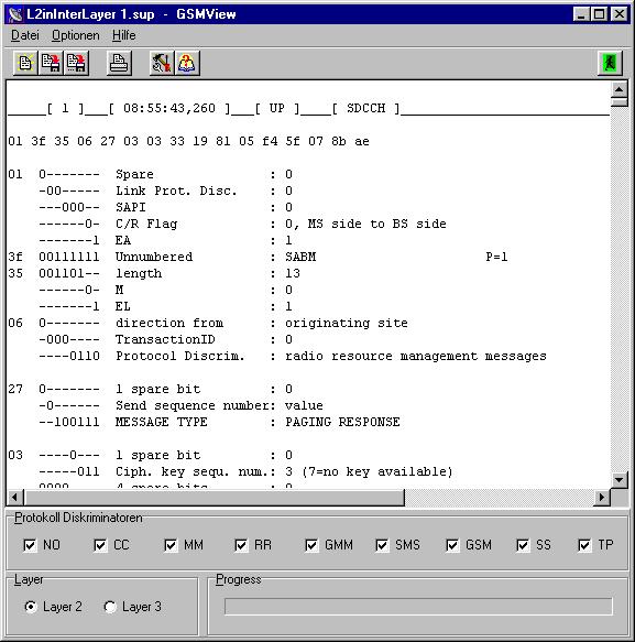
The above picture shows the outfit of the tool. A feature which should be of interest is the possibility to suppress frames of the different protocol discriminators which are not of interest:
| CC: 0011 | MM: 0101 | RR: 0110 | GMM: 1000 | SMS: 1001 | GSM: 1010 | SS: 1011 | TV: 1111 | NO: No information field|
Using the check box Layer 2, only the frames between SABME and DISC get translated.
For instance in the example "Time delay in the ISDN-GSM-field" you find only CC-Messages.
To see the full trace in idle and dedicated mode you have to activate the check box Layer 3. For example see Layer3-Trace of a connection between network and mobile.
In the example Layer 3-Trace-CC there are all PD disabled without PD 03 Call Control Messages.
Another example showing the equivalence between CC-Messages in ISDN and GSM you can find in the above mentioned example "Time delay in the ISDN-GSM-field".
From ISDN we know, teleservices are to be defined in the Information Elements Bearer Capability and High Layer Compatibility. In case of Telephony you may verify that by looking at Layer2-Trace.
If the remote terminal likes to set up a facsimile call, BC and HLC must have the form shown in Layer2-Fax-Trace
As we know that there are a lot of RR Messages, making a trace hard to read, in the facsimile trace RR an MM Frames got filtered out.
If the remote terminal likes to set up a data connection, it has to make the entry unrestricted digital information in the Bearer Capability Information Element. The response of the mobile depends on the operator of the PLMN. First have a look to an example found making a data call from ISDN to D1 network. The trace of the ISDN site is shown in "Data to GSM". Now you can examine the answer of the Mobile in the trace "Data from ISDN".
You can find no Bearer IE in the call from the network. Therefore the OT76 M refuses the call.
The behavior of the network is correct, according to recommendation GSM 04.08 paragraph 9.3.23.1 Setup (mobile terminated call establishment) the presence of the information element Bearer capability is optional.
The operator D2 acts in an other way. As you can see in the trace "Data from ISDN to D2" the call is refused already in the gateway from ISDN to GSM network. The call does not reach the mobile.
You have to distinguish call related Supplementary Service (SS) messages and non call related SS messages. The one will appear in a stream of normal Call Control messages. The other are "stand alone". Both messages are coded in the Abstract Syntax Notation one (ASN.1).
For example the Supplementary Services HOLD and MULTI PARTY SERVICE (MPTY) are call related. The trace was captured by an OT 260. To hold the Trace clearly arranged, only CC-Messages are shown in MULTI PARTY SERVICE. Please follow the trace and have a look at the moment when the user gives the command HOLD to the network. After that, he calls a second subscriber. After being connected with him he calls for the MULTI PARTY SERVICE. The Network will connect the three peers to the "conference bridge" and they can all three talk to each other.
OT76 M allows call forwarding. Please look at the trace activating call forwarding unconditional and the trace deactivating call forwarding unconditional. In both traces the RR frames, known from the example of paragraph 1.2 got filtered. That makes the traces more compact and better to read.
SMS frames can be recognized by its PD=9. There are the messages CP-DATA, CP-ACK and CP-Error. They all are conveyed by an SDCCH, that is, no traffic channel is needed. Layer 3 may pass the whole SMS (more than 140 byte) to layer 2. This stream of date is to be segmented by layer 2 in blocks of 23 byte.
Please have a look to the sample SMS-Trace. It may be of interest that user data are coded in a 7 bit alphabet. There fore 160 characters take (160x7)/8=140 byte. In the shown trace the decoding of the user data (4 character:-)) is demonstrated. Using the RR-filter of GSM-View gives the decoded traced more clearness.
If you like to have a closer look to the GSM-Dm-Channels interpreted by traces captured on the air interface, you can order the book "About the GSM-Dm-Channels" offered by the EPV-Publisher. The book contains a CD with Raw-traces translatable with the tool GSMView, examples, raw-traces and scripts how to translate them. On the CD you find also Power Point-sheets with exercises executed with mobiles usual in the trade or preserved traces, etc..
The General Packet Radio Service (GPRS) represents the possibility to convey data packets over radio channels organized by GSM.
To enable this feature the GSM network had to be extended as shown in the following picture.

To convey packet data over the air interface additional to the 26-Multiframe and the 51-Multiframe (in GSM used to transfer traffic and signalling data), in GPRS a 52-Multiframe is added to build the Packet Data CHannels PDCH.
In spite of the fact that GPRS knows a similar number of logical channels as GSM, not all of the possible PDCH's are mandatory present. As you can see in the following traces for instance the Broadcast and Control Channels of GSM are used. The only used GPRS typical channels are the Packet Data Traffic Channel PDTCH and the Packet Associated Control CHannel PACCH.
In Circuit Switched Technology of GSM, the mobile, if switched on by the user, acts as follows:
It reads the SYSTEM INFORMATIONS sent by the Broadcast Control CHannel of its Cell, finds in the message SYSTEM INFORMATION TYPE 1 the frequencies of Broadcast- and Traffic Channel, finds in the message SYSTEM INFORMATION TYPE 2 the beacon frequencies of the neighbor cells. In SYSTEM INFORMATION TYPE 3/4 it reads about the location it resides in and some other features. With the gained Information the mobile can pre tune its components.
Now the mobile has to request a Channel to send a LOCATION UPDATE REQUEST and after some negotiations it waits for, either a PAGING REQUEST from the network calling its IMSI / TMSI, or the user of the mobile sets up a call.
In both cases the mobile gets in an IMMEDIATE ASSIGN message a Slow Dedicated Control Channel and the time slot, building the channel to convey all the necessary control data information between the peers of the now active communication line.
In packet switched technology of GPRS, relating to LOCATION UPDATING REQUEST, the mobile acts like in case of GSM:
After the LOCATION UPDATING REQUEST the mobile looks for the presence of a SYSTEM INFORMATION TYPE 13 message on the BCCH.
If it finds one, it reads some important values relating to GPRS Mobile Allocation, GPRS Cell Options, GPRS Power Control Parameter and so on.
Now the mobile initiates an ATTACH REQUEST. After that, the network starts an AUTHENTICATION REQUEST followed by an IDENTITY REQUEST. If the negotiation is successful the network sends an ATTACH ACCEPT. The answer of the Mobile is ATTACH COMPLETE.
In the Trace GPRS-ATTACH you can find the whole procedure beginning with the LOCATION UPDATING REQUEST in frame number 23, followed by a channel request and an ATTACH REQUEST. The trace was captured using an OT 290.
Pleas pay attention that there are two sequences of commands following one after another. First there is the Location Updating procedure, only a simple SDCCH is necessary to do so. After the radio channel was released a new IMMEDIATE ASSIGNMENT follows, which now dedicates a temporary block flow. The communication between mobile and network takes place now by conveying data blocks, not to be seen in the trace.
The network now starts an AUTHENTICATION REQUEST followed by an IDENTITY REQUEST. After this communication was successful the network sends an ATTACH ACCEPT and the mobile answers with ATTACH COMPLETE.
You have to keep in mind, that all messages sent in GPRS are send in packed mode.That is, the message ATTACH REQUEST is packed up in a LLC frame before conveying it over the radio channel.
After the mobile is registered by the network (ATTACH ACCEPT), it is possible to order an IP-number ( a PDP context ) from the network. If the IP-number is granted, the mobile acts as a terminal (always on) in the world wide Internet.
To request a context the mobile has to send a ACTIVATE PDP CONTEXT REQUEST message. Amongst other parameters this message contains:
- The Packet data protocol type (e.g. IPv4),
- the Access Point Name (to identify the GGSN of the operator),
- the Quality of Service (QoS) profile (e.g. Priority, Delay Class, Mean and Peak Troughput rate and Reliability Class) and so on.
The network should answer the request using the message ACTIVATE PDP CONTEXT ACCEPT. The latter contains the granted QoS parameter and the IP-number.
You can see this handling in the trace PDP_Context_Request.
After the PDP context exists, the GPRS-connection is usable like a LAN-connection. If you are familiar with the rules an commands of TCP/IP you may verify this by means of the following example, when a PING-command is issued on the computer the mobile is connected with.
In frame number 4 you find a PING-command embedded in a LLC-frame.
In frame number 5 The mobile sends a CHANNEL REQUEST "One phase packet access with request for single time slot up link transmission; one PDCH is needed".
In frame number 27 a Temporary Block Flow (TBF) is assigned. Now it is possible to send the LLC-frame to the network.
The LLC-frame is split into 5 blocks for transmission over the air-interface.
In frame number 27 retransmission is requested as the TBF is incomplete. Only the first transmitted block was intact.
In frame number 28 retransmission is requested as the TBF is incomplete. Only four transmitted blocks were intact.
In frame number 34 a receipt is given that all 5 blocks are transmitted without any trouble.
In frame number 30 a down link channel is assigned.
In frame number 31 this assignment is accepted by the mobile.
In frame number 32 the network sends the answer to the ping.
Please follow the trace and interpret it by your self.
You must be a little familiar with Walsh Functions to understand the basic mode of operation in UMTS.
The frequency band for Frequency Division Duplex in UMTS covers uplink 1,92..1,98 GHz and downlink 2,11..2,17 GHz. This frequency band is divided into 6 blocks of an bandwidth of 9.9 MHz. Every block belongs (in Germany) to one operator. The working frequency in this block is modulated with an impulse rate of 3,84 million chips per second (Mcps). To have a difference to the desired signal which is measured in bits, the impulses with which the carrier frequency is modulated are measured in chips.
As we like to modulate this carrier with more than one channel we use the law of a Walsh-tree. Please have a look at the tree beneath. Channelization means to applicate the different orthogonal codes given by the branches of the tree (and their OSF) for the different data streams. Every data stream has a frequency of 3,84 Mcps. But the greater the Spreading Factor the greater the number of chips building a data symbol (bit), the smaller the frequency of the modulated signal.
Lets have an example. The branch of spreading factor 8 (SF8) represents a theoretical data rate of 480 Kbit/sec. As there is some overhead, we get a real transmission rate of 384 Kbit/sec.
You can see in the picture above, that the thick red code line Cch,8,2 is related to its father, its sons, grand sons and so on. All these codes cannot be used if Cch,8,2 is active.

There are some reasons why the codes, build using the Walsh-functions, are to be modulated once more with a pseudo noise sequence of 3,84 Mcps.
With the greater bandwidth it is possible to change much more information between Mobile and Node B and you will see beneath that the traces will be harder to read.
As you can see from the following picture the GSM/GPRS network and the UMTS network are brought together in the "Mobile Core Network". If you are subscriber of GSM/GPRS and at the end of the period of validity of the agreement with your operator you wish to change to UMTS, you get an UMTS-mobile to a lower price and you can retain your SIM-card (with your phon number). Your new rights are only updated in the HLR (which use GSM/GPRS and UMTS together).
That is, no special USIM is needed as it is written in some books. With the same mobile you may communicate in the UMTS-network, or, if not available in the GSM/GPRS-network.
The Node B in the Radio Network Subsystem plays the role of the BTS in Base Station Subsystem and the RNC (with much more functions) plays the role of BSC. The Iur interface of the RNC serves the connection between neighboring RNC and allows Soft-Handover.
As mentioned above, the from GSM known Call Control messages, Supplementary Services, SMS, Mobility Management services are further more in use in UMTS. The same as the Mobility Management messages for GPRS services and the Session Management messages of GPRS. They all are called to reside in the Non-access stratum. The term Stratum had been chosen, as the term Layer is already in use. Please have a look to the next picture.
The modulation principle in GSM allows only to build messages of 23 octet length. In contrast to GSM, UMTS allows (as mentioned above) to build channels with a higher data rate and messages of a length of more than 100 octet. You can verify this in the traces shown in the next paragraphs.
While in ISDN, GSM and GPRS only some messages are coded in ASN.1, without exception in UMTS the RRC-Messages are coded in "Packet ASN.1 (PER:ITU-T Recommendation X.691)".
If you are some familiar with ASN.1 you can decode the RRC-Messages as defined in ETSI TS 125331. Beginning this task you will soon brood over the problem how to handle the optional Information Elements, or how to deal with the range of a given variable. The solution of this problem is quite easy (you must only know it :-). You can find the How To in the library demo of inacon (http://www.inacon.com/library/demo/index.php). You will find there an example how to decode the message rrcConnectionRequest.
In the paragraphs 1..5 of these script I used to explain the rules of mobile communication, for teaching purposes, by explaining the traces captured from the air interface. To continue doing so it was necessary to think it over, where from can I get traces from the UMTS-air-interface. There were some possibilities:
- To take the traces from the Iub interface of the Node B captured by a Tektronix trace-tool. Result of reflection: Not possible, as to expensive and the not answered question, how should a teacher get access to the Radio Network System?
- To capture the trace with a Qualcomm-trace-mobile and decode with Friendly Viewer. Result of reflection: Capture traces on the air-Interface is possible but too expensive for teaching purposes.
- our solution: Mr. Sebastian Göller wrote, as already done for ISDN and GSM/GPRS, a translator for UMTS-Traces, given in hex-format, and I had to write the scripts to translate the traces ETS-conform, a hard work :-( . Please have a look to he following picture. You can see the filter to separate the different channels and the possibility to tune in "line numbers" in each message. The question is where from do we get raw traces to translate them as for example RRC CONNECTION REQUEST.
- To capture the traces with a Motorola E1000? Not possible, as the company does not answer my request for selling me the interface to do so.
- I think the solution will be to wait for SAGEM untill they finish the development of their trace tool for UMTS and the possibility to export the traces in the well known manner.
Lets now go on to interpret the mode of operation of an UMTS-mobile by considering the messages on the air interface.
In GSM/GPRS connection establishment is organized by Radio Resource (RR) messages. In UMTS this task is performed by Radio Resource Control (RRC) messages. While in GSM/GPRS only a Channel Request on the RACH is sent. In UMTS the Channel Request procedure is some what more sophisticated.
In UMTS (CDMA-systems) power control is a very important task. It is needed to minimize the interference in the system. A subscriber, sending with a too high power can block the whole system. There fore a subscriber who wants to start a connection, that means wants to get a channel, has to act in the way as shown in the following picture.
The contents of the message RRC-CONNECTION REQUEST is shown in the following trace. At the beginning of the trace you find some switches. As explained in paragraph 6.2, they are due to the Information Elements in the message which are optional.
Answering the RRC CONNECTION REQUEST message the network returns the message RRC CONNECTION SETUP. To read the contents of this message requires some knowledge about channels in UMTS and the role of Radio Bearers. It is not intended to teach about this here. To have an overview, you can look for the sections
⇒ User equipment IEs, which consist the PLMN-identity and some other reference numbers.
⇒ Radio bearer IES, there are four radio bearers which are generated. One of them uses the Unacknowledged Mode, three of them are using Acknowledged Mode. All together build a DL-DCH transport channel and a logical DCCH.
⇒ Transport channel IEs, which describe the Uplink-DCH and the Downlink-DCH, with the Transport-Channel-Identity, the Physical Channel Type, the Time Transmission Interval, the Convolutional Coding Type etc.
⇒ Physical channel IEs, which consist among other things the Scrambling Codes and the Spreading Factor.
After the mobile got the message rrcConncetionSetup it tunes its components corresponding to the values handed over and answers by RRC CONNECTION SETUP COMPLETE. Now the mobile has to announce to the network.(Please have a look to the following picture "Loaction Update in Circuit Switched Mode")
This is done by the message, well known from the GSM/GPRS, LOCATION UPDATING REQUEST. Please notice a special feature, the message LOCATION UPDATING REQUEST is not transmitted direct to the Node B, but is packet up into the message INITIAL DIRECT TRANSFER. By this message it is sent as NAS-message on the Uplink dedicated physical channel UL_DPCH to the network.
Please keep in mind: All NAS-Messages are transported in Uplink-, Downlink- or Direct-transfer messages over the air interface.
As the principle of packaging the NAS-Messages into the messages INITIAL-,UPLINK- or DOWLINK-DIRECT TRANSFER is generally valid in UMTS, you will find in the UMTS Trace of a telephone call without the from GSM known messages only a few UMTS-typical.
In the shown graphic only the messages SECURITY MODE COMMAND and RADIO BEARER SETUP are UMTS-typical.
Last update on 2006-01-13 – Will be continued :-)